Fire Sprinkler Hydraulic Design Information Sign: What Goes On It and Where It Goes
The inspector asks for the hydraulic design information sign at the riser and yours is missing, unreadable, or lists numbers that no longer match the as-built calculations. Here is what belongs on it, where the numbers come from, and how to mount it.
Important Disclaimer
This article is provided for general informational purposes only and does not constitute legal, safety, or professional compliance advice. Regulations, standards, and codes are subject to change and may be interpreted differently by authorities having jurisdiction (AHJ). Always consult with qualified safety professionals, licensed engineers, or legal counsel to determine the specific requirements applicable to your facility. TagBuilder is not responsible for any actions taken based on this information.
A hydraulic design information sign is a permanent plate at the control valve or riser of a hydraulically calculated sprinkler system. It records what the system was designed to do: the design area, the discharge density, the flow and pressure needed at the base of the riser, the occupancy or storage it was designed for, the hose stream allowance, and the contractor who installed it. The numbers come straight from the hydraulic calculations, not from the sign maker.
Why the sign matters after the job is closed
On the day of acceptance, the sign is one of the first things an inspector looks for at the riser. If it is missing, or the numbers disagree with the calculation package, the usual result is a punch-list item and a return trip.
The longer-term cost is quieter. Years later, someone wants to change the occupancy, raise the storage height, or add a mezzanine. The plate at the riser is often the only quick way to see what the system was designed to protect. Without it, the next engineer has to dig for the original calculations, and a periodic inspector under NFPA 25 has nothing to compare against.
What NFPA 13 asks for, in plain terms
NFPA 13 has a section for hydraulic design information signs and, in newer editions, a separate section for a general information sign. The section numbers move from edition to edition, so check the edition your AHJ enforces and read the current text. What follows is a paraphrase, not the standard's wording.
- Durable and permanent. The sign is commonly metal or rigid plastic, with lettering that will not wear off or rub away.
- Secured at the riser. It is commonly attached with corrosion-resistant wire or chain, or fastened directly, at the control valve or riser serving the hydraulically designed area.
- Specific content. The sign carries the design data for the area it serves, as listed in the next section.
- One sign per hydraulically designed system or riser. A building with several risers usually needs several signs, each with its own numbers.
Some fire departments and AHJs also specify their own layout, minimum letter height, or wording. If yours does, that local requirement controls what you build.
What goes on the sign and where each number comes from
The table below lists each typical field, an invented example entry, and the place in the hydraulic calculation package where the number comes from. Use it as a checklist when you pull the data together.
| Field | Example entry | Where it comes from in the calc package |
|---|---|---|
| Location of design area(s) | Second floor, east wing, remote area | Design area description and the sheet or plan that marks the remote area |
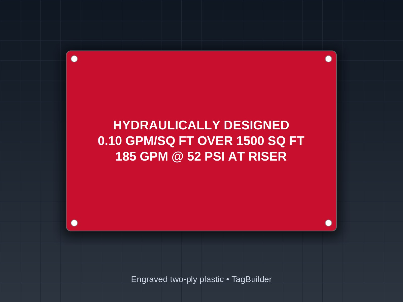
| Discharge density | 0.10 gpm/sq ft over 1,500 sq ft | Design criteria summary, usually the first page of the calculation |
| Required flow at base of riser | 268 gpm | Summary result at the riser node, including the hose allowance |
| Required residual pressure at base of riser | 52 psi | Same riser node line in the results |
| Occupancy or commodity class, max storage height | Light hazard, office occupancy | Design criteria and hazard classification; storage height applies where the design depends on it |
| Hose stream allowance included | 100 gpm | Hose stream line in the design criteria |
| Installing contractor | Company name, city, license or phone | Your own contract and project records |
Copy the values from the final, as-built calculation, not from an early bid version. If field changes altered the pipe sizes or the remote area, rerun the calculation first and then make the sign.
The general information sign in newer editions
Newer editions of NFPA 13 also call for a general information sign at the riser with items beyond the hydraulic data. Depending on the system and the edition, these can include things like the type of system (wet, dry, preaction), whether antifreeze is used, the presence of a dry pipe valve or other special components, and water supply or flow test information. Some AHJs want these on the same plate and others want a separate one.
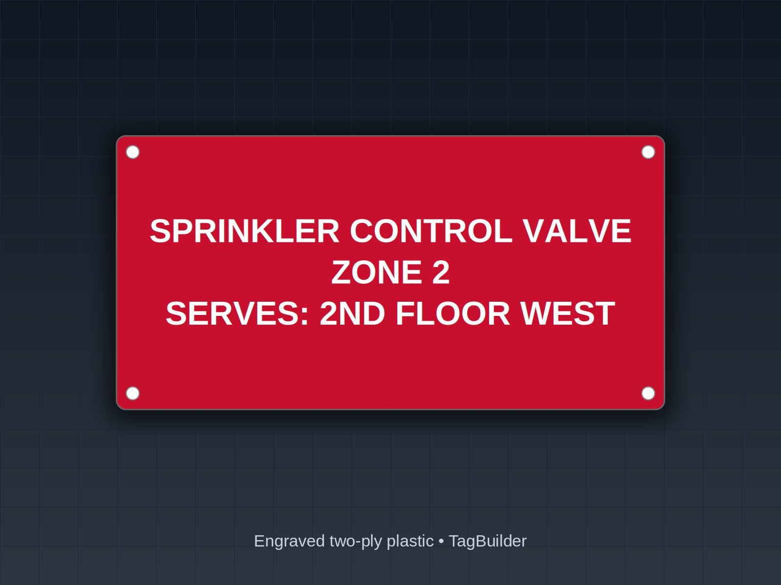
Do not guess. Confirm with the AHJ whether it wants one combined plate or two, and which edition's list it is working from. Our guide to fire sprinkler control valve signs covers the identification signs that sit alongside this one.
A worked example: light-hazard office floor
The entries below are an example only, with invented but realistic numbers. Your sign must carry the values from your own approved-for-submittal calculations and whatever wording your AHJ asks for. Use this as a layout to copy line for line.
- Heading: HYDRAULIC DESIGN INFORMATION
- System / Riser: Riser 2, Wet Pipe, Floors 2 and 3
- Design area location: Floor 2, east wing, remote area
- Occupancy classification: Light hazard (office)
- Design density: 0.10 gpm/sq ft
- Design area: 1,500 sq ft
- Hose stream allowance included: 100 gpm
- Required flow at base of riser: 268 gpm
- Required residual pressure at base of riser: 52 psi
- Calculation date / reference: Calc no. 24-117, rev. B
- Installed by: Example Fire Protection Co., Anytown, USA, (555) 555-0100
Eleven lines like this fit on a plate about 6 x 4 inches in a small, readable type. If your AHJ adds items, move up in plate size rather than shrinking the letters further.
Plate size, letter height, and material
This sign carries more text than a valve tag, so it generally needs a larger plate. 6 x 4 inches is a common starting point, and 8 x 5 or larger is normal when the general information items are on the same plate.
For letter height, a heading around 3/8 inch and body lines around 3/16 inch is a workable range on a plate that size. Anything much smaller gets hard to read in a dim riser room. If your AHJ states a minimum letter height, use it.
- Engraved two-ply plastic is a common choice. The text is cut into the surface, so it does not rub off the way printed ink can. White letters on a red face matches most fire protection signage, and black on white is easier to read when there are many lines.
- Engraved stainless suits damp, dusty, or outdoor risers and where the AHJ asks for metal.
- Holes in the corners let you hang the plate on chain or wire. Four holes also allow screw mounting to a wall.
Mounting on the riser
Hang the plate from the control valve or the riser with corrosion-resistant chain or wire, at a height where an inspector can read it without moving anything. Do not hide it behind piping, and do not mount it where a door swing will cover it. Our valve tag attachment guide compares chain, cable ties, and fasteners for different conditions.
Plan to make the sign when the final calculation is issued so it is on the riser before the acceptance walk-through, not after it.
Frequently Asked Questions
What goes on a sprinkler hydraulic placard?
Commonly the design area location, discharge density, required flow and residual pressure at the base of the riser, occupancy or commodity classification and storage height where it applies, the hose stream allowance, and the installing contractor. Check the edition of NFPA 13 your AHJ enforces for the exact list.
Where does the hydraulic design information sign go?
At the control valve or riser that serves the hydraulically designed area, attached so it stays with that riser. In a building with several risers, each one gets its own sign with its own numbers.
Is a hydraulic nameplate the same as the general information sign?
No. The hydraulic sign records the design criteria and results. The general information sign, called for in newer editions, records items such as system type and antifreeze. Some jurisdictions accept both on one plate, so ask the AHJ.
What size should an NFPA 13 hydraulic data plate be?
The standard does not give one size for every job. Plates around 6 x 4 inches are common for a basic sign, and larger when more items are included. Follow any letter height your AHJ specifies and keep the text readable from a normal standing position.
Who supplies the numbers for the sign?
The sprinkler designer or contractor, from the final hydraulic calculations. We lay out and engrave what you send, and we do not calculate or check the design data.
What if my riser is missing its sign years after install?
Get the original calculations from the contractor, the building owner, or the AHJ file, confirm the system still matches them, and have the sign made from that data. If the occupancy or storage has changed, a designer should review the system first.
Send us the numbers from your hydraulic calc and we'll lay out and engrave a sample design sign and mail it, no charge.
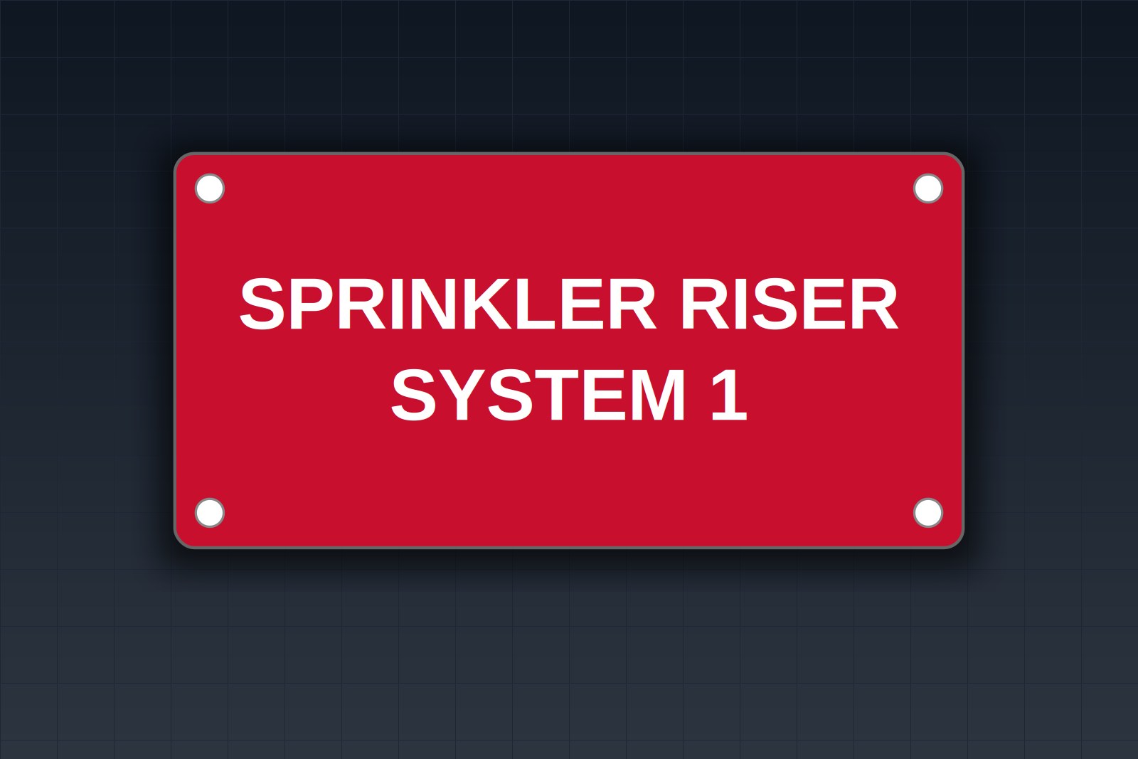
For the rest of the riser, the stock SPRINKLER RISER sign and FIRE valve tags cover the identification side, and the free engraved sample is the easiest way to see how your hydraulic data fits on a plate before you order.
UL, NFPA, NEC, ASME, CEMA, TIA, ANSI and OSHA are names or marks of their respective organizations; TagBuilder is not affiliated with or endorsed by any of them. Requirements above are paraphrased summaries, not the text of any standard. Always work from the current published edition and your AHJ.