MCC Bucket Nameplates: What to Engrave on Each Unit Door
You are labeling a new motor control center or re-labeling an old one after a retrofit, and the doors all look the same. If the plates do not match the one-line and the motor list, the next person standing at the lineup is guessing which bucket kills which pump.
Important Disclaimer
This article is provided for general informational purposes only and does not constitute legal, safety, or professional compliance advice. Regulations, standards, and codes are subject to change and may be interpreted differently by authorities having jurisdiction (AHJ). Always consult with qualified safety professionals, licensed engineers, or legal counsel to determine the specific requirements applicable to your facility. TagBuilder is not responsible for any actions taken based on this information.
Start With the Naming Rule, Not the Plates
Every plate on the lineup should be derived from one source: the one-line diagram and the motor list. Pick the naming rule first, write it down, and engrave from the list. Re-typing names from memory at the bench is how a pump ends up as P-3 on the door, PMP-3 on the drawing and Pump 3 on the HMI.
A scheme that holds up in the field has three parts:
- Lineup and section: MCC-1, then section number counted left to right facing the front.
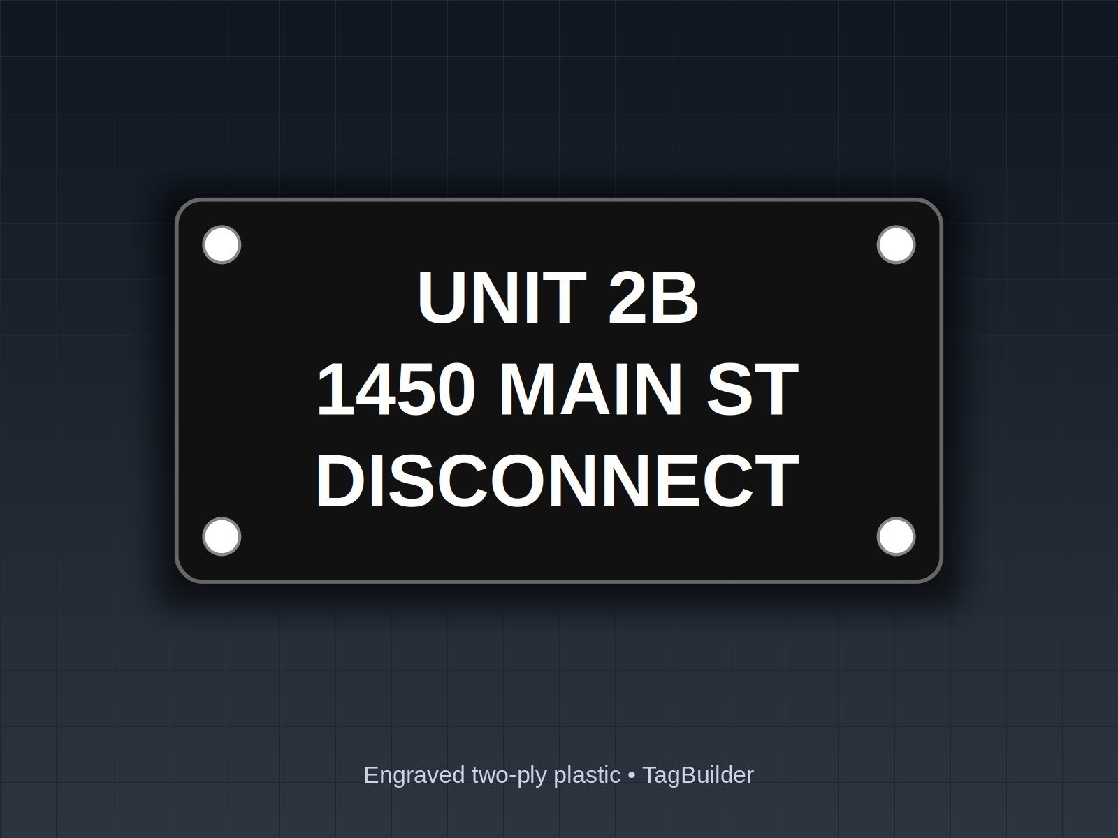
- Unit number: section number plus bucket position from the top, such as 3B. This is what maintenance says out loud on the radio.
- Load tag: the equipment tag from the P&ID or motor list, such as PMP-3, followed by a plain-English service.
Keep the load tag identical to what the plant already uses. If the plant calls it SLUDGE PUMP 3, do not shorten it to SP3 on the door.
The Section and Lineup Plate
The lineup plate goes at the top of the first section, or on the end of each section if the lineup is long. It answers three questions before anyone opens a door: what is this, what is it fed from, and what voltage is inside.
The source line follows the same practice that NEC 408.4(B) uses for switchboards and panelboards: mark where the supply originates. MCCs are not always treated as a 408 product, so confirm with your AHJ, but most plants want the feeder source on the plate anyway. Check the current edition for the exact wording of the requirement.
Sample section plate (4 lines):
- MCC-1 — SECTIONS 1 THRU 4
- 480 V, 3 PH, 3 W, 60 HZ
- FED FROM: SWBD-MAIN, FEEDER F-12
- BUS RATING: 600 A
Use the nominal system voltage and the bus rating from the nameplate on the gear itself. Do not copy numbers from an old drawing without checking them.
What Goes on Each Bucket Door
A bucket door plate is a short label. It has to be readable from a step back, on a door that may be wearing a lockout hasp and a handle. Keep it to the facts maintenance needs to isolate the load:
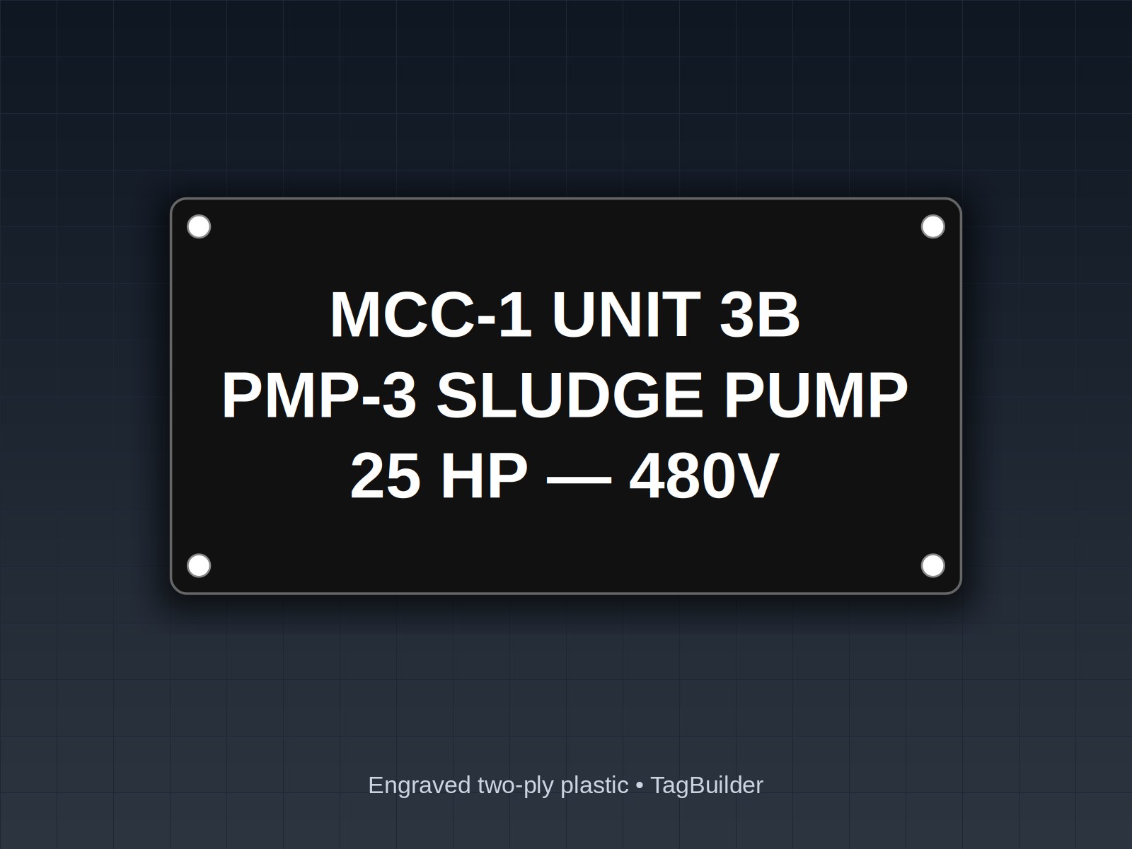
- Unit number (3B), large and on the first line.
- Load tag and service (PMP-3 SLUDGE PUMP).
- Rating (25 HP, 480 V) so a replacement is sized correctly.
- Protection and starter size (breaker frame and trip, or fuse class, plus starter size such as NEMA 2). Verify these against the as-built bucket, not the original submittal.
Disconnect identification and 430.102
The disconnecting means in each bucket is the operating handle. NEC 430.102 deals mainly with where the controller disconnect and the motor disconnect must be located, so many AHJs expect the plate to let someone find and confirm the right disconnect for the right motor. Separately, the general rule on disconnect marking (commonly cited as 110.22) calls for legible markings that state the purpose. In practice that means the load tag on the door must be unambiguous. If the motor is out of sight of the bucket, many plants add a line such as MOTOR LOCATION: BLDG 2 LIFT STATION. Section numbers vary by edition and local amendment, so check yours.
Operator Legends: HAND-OFF-AUTO and Pilot Lights
Operators on the door need their own legend plates, mounted under or around the device. Typical legends:
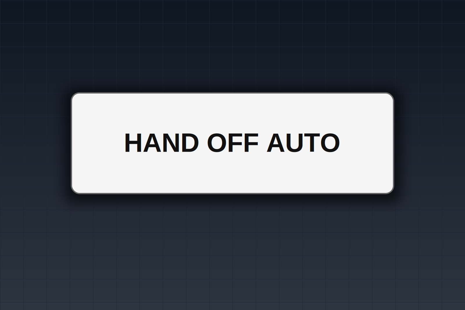
- HAND – OFF – AUTO for the selector switch
- START / STOP, or FWD / REV / OFF where applicable
- RUN, FAULT, OVERLOAD TRIP and similar pilot light labels
- RESET for an overload or fault reset button
Legend plate dimensions follow the operator manufacturer's mounting hardware. As a rough guide, 22 mm operators commonly take a plate in the neighborhood of 30 by 50 mm, and 30 mm operators take a larger plate, but the exact size and the way the plate retains varies by brand and series. Confirm the dimensions and the plate style against the operator before you order. For a custom run, our rectangle plate builder lets you set size, text and hole positions.
Plate Types and Sample Text
| Plate | Where it goes | Typical size | Sample text |
|---|---|---|---|
| Lineup plate | Top of first section | 6 x 3 in | MCC-1 / 480 V 3 PH / FED FROM SWBD-MAIN |
| Section plate | Top of each section | 4 x 1 in | MCC-1 SECTION 3 |
| Bucket plate, 6 in door | Upper door face | 4 x 1.5 in | 3A / PMP-3 SLUDGE PUMP / 25 HP |
| Bucket plate, 12 in door | Upper door face | 4 x 3 in or 5 x 2 in | 3B / PMP-3 SLUDGE PUMP / 25 HP 480 V / NEMA 2 |
| Operator legend | Under switch or light | Per operator mount | HAND OFF AUTO |
| Arc flash plate | Front of lineup | Per your label program | Site-specific, from the study |
| Spare / space | Empty bucket door | 4 x 1.5 in | 3D / SPARE |
On a 6 in door there is room for one load line and one rating line. If you cannot fit the starter size, put it on a second plate inside the door where the next person will see it when the bucket is open. A 4 by 1.5 in plate is a common choice for 6 in doors, which is why we stock it as a ready-made MCC unit label.
The Arc Flash Plate on the Lineup
NEC 110.16 calls for field marking of certain equipment, and an MCC is one of the types that section names, to warn qualified persons of arc flash hazard. The label is separate from your bucket plates. The numbers on it come from your arc flash study and your site program, not from us, and they change when the system changes. See our arc flash label guide for what the study-based labels carry, and check the current edition of both the NEC and NFPA 70E for the content your AHJ expects.
Two-Color Plates for Critical Loads
Many plants use color to separate load classes at a glance. A common practice is a plain black-on-white or white-on-black plate for normal loads, and a contrasting color for loads that matter during an emergency or an outage:
- Red background for fire pumps, emergency ventilation or life safety loads.
- Yellow background for loads on a standby or generator-backed bus.
- Plain white for everything else.
No single national color scheme covers every plant, so write your colors into the site labeling standard and use them consistently. Engraved two-ply plastic gives you the color by the plate stock itself, and the engraved text does not rub off like printed ink.
Worked Example: A 12-Bucket MCC Label List
This list is built from the motor list first, then checked against the one-line. Unit numbers are section plus position from the top. Copy the layout and swap in your own tags.
| Unit | Load tag and service | Rating | Door | Color |
|---|---|---|---|---|
| 1A | MAIN FEEDER BREAKER | 600 A | 12 in | White |
| 1B | PMP-1 RAW SEWAGE PUMP | 40 HP | 12 in | Red |
| 1C | PMP-2 RAW SEWAGE PUMP | 40 HP | 12 in | Red |
| 2A | BLR-1 BLOWER | 30 HP | 12 in | White |
| 2B | BLR-2 BLOWER | 30 HP | 12 in | White |
| 2C | PMP-3 SLUDGE PUMP | 25 HP | 12 in | White |
| 3A | PMP-4 SLUDGE PUMP | 25 HP | 6 in | White |
| 3B | MXR-1 MIXER | 10 HP | 6 in | White |
| 3C | EF-1 EXHAUST FAN | 5 HP | 6 in | Yellow |
| 3D | CMP-1 AIR COMPRESSOR | 7.5 HP | 6 in | White |
| 4A | XFMR-2 PANEL LP-2 FEED | 45 kVA | 12 in | White |
| 4B | SPARE | — | 12 in | White |
Before ordering, do three checks. First, every load tag appears once in the motor list and once on the one-line. Second, every horsepower matches the motor nameplate, not the design basis. Third, any bucket that was swapped in a retrofit gets a new plate, not a patch over the old one.
Frequently Asked Questions
Do I need a plate on every bucket, including spares?
Yes, as a practice. A spare plate with the unit number tells the next electrician which bucket is which, and the plate gets updated instead of replaced when the space is used. Check whether your AHJ or plant standard asks for more.
Can I put the arc flash data on the bucket plate?
It is better to keep it separate. Arc flash values are tied to a study and need to be revised on their own schedule, so a separate label is easier to replace without touching the bucket identification.
What text height is readable on a bucket door?
Most plants use a letter height around a quarter inch for the unit number and load tag on a bucket door, and smaller for the rating line. Pick a size that reads from standing distance, not from the bench.
Should the plate be riveted, screwed or adhesive-backed?
Door finish and vibration decide this. Mechanical fasteners hold on painted steel doors where adhesive may lift with age, but do not drill through a door in a way that affects the enclosure, and check with the gear maker first.
How do I handle a retrofit where buckets move?
Re-number from the new one-line, update the motor list, and remove the old plates rather than leaving two names on one door. Keep the old-to-new unit table in the maintenance file for a year or so.
Will these plates satisfy an inspector?
We cannot say what a given inspector will accept. Show the AHJ your labeling plan and the sample plates before you engrave the full lineup.
Send one bucket number and the load it serves and we'll engrave a sample MCC plate and mail it, no charge.
If the lineup also feeds drives, see our notes on VFD warning labels under NEC 430, and browse motor and equipment labels for ready-made stock. To see how an order moves from your list to your dock, read how it works.
UL, NFPA, NEC, ASME, CEMA, TIA, ANSI and OSHA are names or marks of their respective organizations; TagBuilder is not affiliated with or endorsed by any of them. Requirements above are paraphrased summaries, not the text of any standard. Always work from the current published edition and your AHJ.