Motor Disconnect and Controller Labels: NEC 430.102 and 430.110 in Practice
You are standing in a mechanical room with four motors, four disconnects and four starters, and nothing on any of them says which pump or fan it controls. This is how to label them so the next person can find, identify and lock out the right one.
Important Disclaimer
This article is provided for general informational purposes only and does not constitute legal, safety, or professional compliance advice. Regulations, standards, and codes are subject to change and may be interpreted differently by authorities having jurisdiction (AHJ). Always consult with qualified safety professionals, licensed engineers, or legal counsel to determine the specific requirements applicable to your facility. TagBuilder is not responsible for any actions taken based on this information.
Which NEC sections touch motor labeling
Four sections do most of the work on a motor circuit. None of them is a labeling article by itself, but together they decide what a disconnect or controller plate needs to say. Section numbers and wording shift between editions, so check the edition your jurisdiction has adopted.
| Section | What it deals with | What it means for the plate |
|---|---|---|
| 430.102 | Where the disconnecting means goes relative to the controller and the motor | Drives whether you need a location marking when the disconnect is out of sight |
| 430.110 | Ampere rating of the disconnecting means | Rating is commonly shown on the equipment itself; your plate should not contradict it |
| 110.22 | Disconnecting means must be marked to show its purpose, unless the purpose is evident | The plate names the equipment served |
| 430.8 | Controller marking: maker, voltage, current or horsepower rating, short-circuit rating | This is the manufacturer's nameplate; do not cover it |
For the general identification rule across all equipment, see the guide to 110.22 disconnect identification labels. This article stays on motor circuits.
NEC 430.102: sight lines and lockable disconnects
Controller disconnect
In general, 430.102 asks for a disconnecting means within sight of the controller it serves. "Within sight" is defined in Article 100 as visible and not more than 50 ft away. A controller in a motor control center, a starter on a wall, or a combination starter with a built-in disconnect usually meets this without further thought.
Motor disconnect
The code also calls for a disconnecting means within sight of the motor and the machinery it drives. There are exceptions. A common one allows the controller disconnect to serve both jobs when it can be locked in the open position and meets the conditions in the exception, such as a separate disconnect being impracticable or adding hazards. Many facilities also expect written lockout procedures in that case. Whether your installation qualifies is a question for the engineer of record and the AHJ.
Why this matters for labels
Lockout only works if the person holding the lock is sure which circuit they have isolated. A plate that reads the equipment tag removes the guesswork. It does not replace the lockout procedure, and it does not change who is responsible for it.
NEC 430.110: the ampere rating
Section 430.110 sets the minimum ampere rating of the disconnecting means for a motor circuit. For a typical single motor, it is commonly worked out as at least 115 percent of the motor full-load current taken from the NEC tables, not from the motor nameplate. For illustration only: a motor with a table full-load current of 14 A gives 16.1 A, so a disconnect rated 30 A would be a typical standard size. Combination loads, torque motors and other special cases use different methods.
You do not have to print the rating on a plate, since the switch or breaker usually carries its own rating. If you do add it, copy it from the installed device. A plate that says 30 A on a 60 A switch causes more trouble than no rating at all.
NEC 430.8: leave the controller nameplate alone
The manufacturer's controller marking covers maker, voltage, current or horsepower rating and short-circuit current rating. That information belongs to the listed equipment. Your engraved plate is a second, separate plate that identifies the load and its source. Mount it beside the factory nameplate, not over it, and not over vents, wiring diagrams or warning labels.
If the circuit has a variable frequency drive, there are additional warnings to consider. Those are covered in the VFD warning label article, so they are not repeated here.
Worked example: a mechanical room schedule
Assume a mechanical room with two chilled water pumps, an exhaust fan and an air handler. The values below are made up for the example. Replace them with your own equipment schedule and panel directory.
| Equipment tag | Disconnect plate text | Controller plate text | Cross-reference on both plates |
|---|---|---|---|
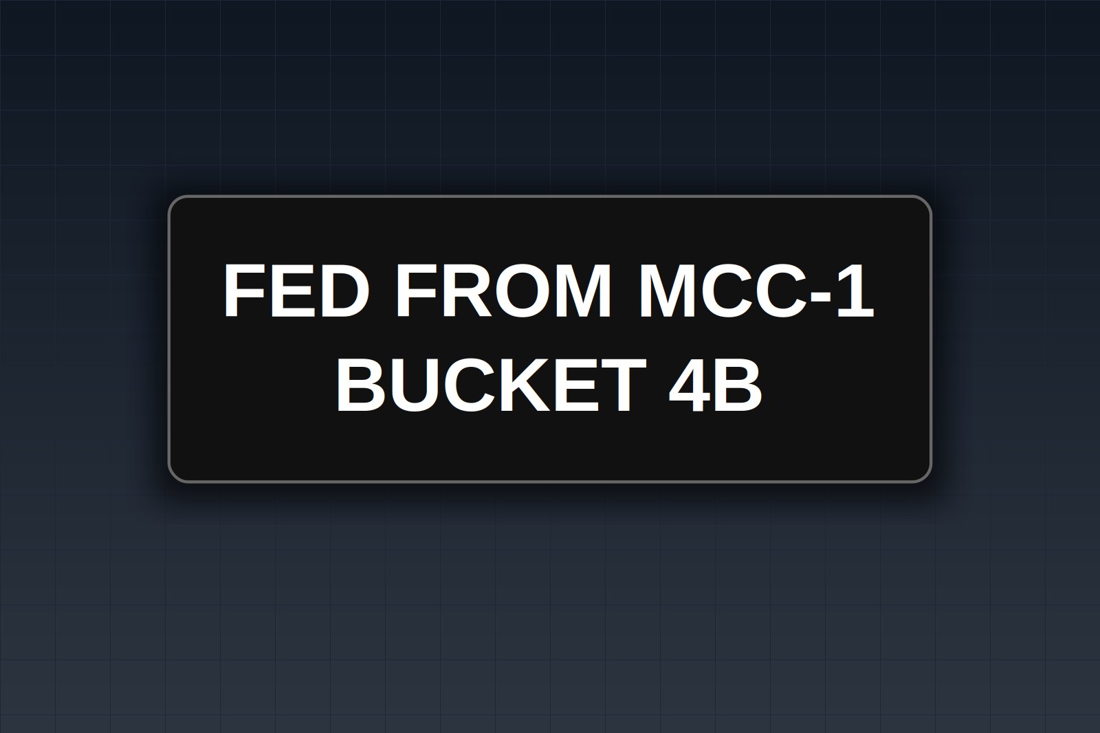
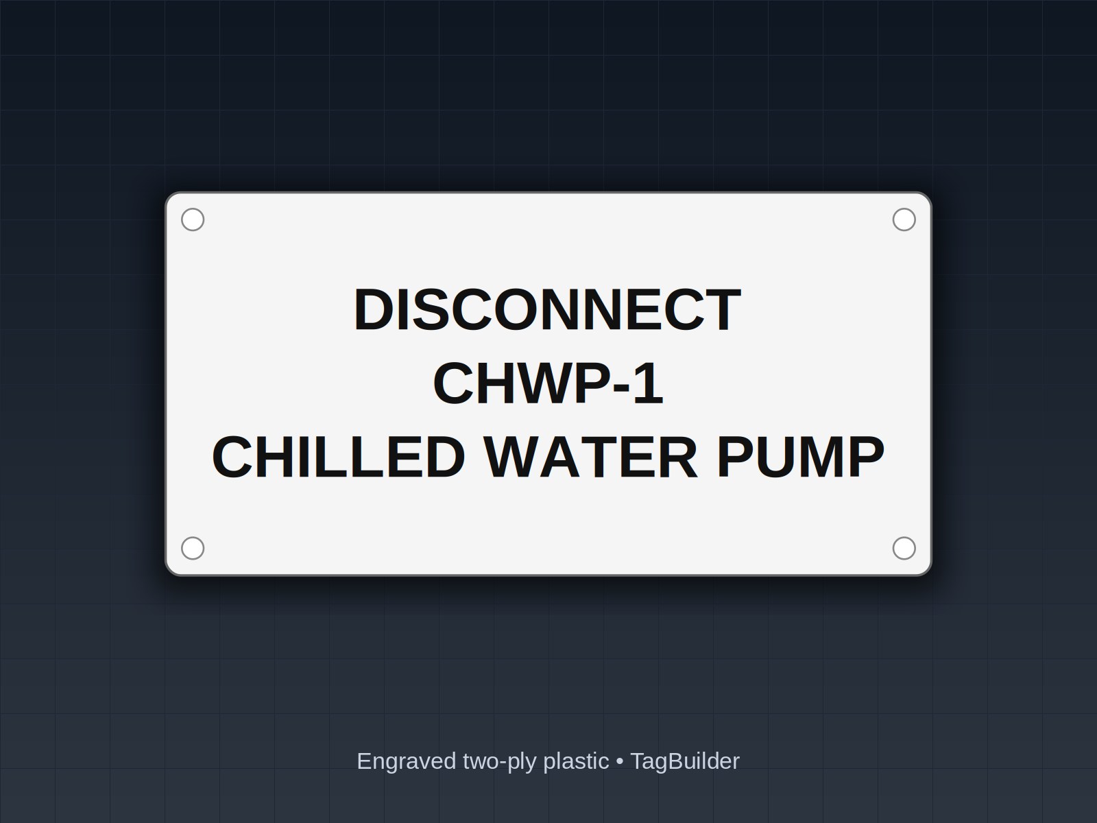
| CHWP-1 | DISCONNECT CHWP-1 CHILLED WATER PUMP 1 | STARTER CHWP-1 CHILLED WATER PUMP 1 | FED FROM PANEL MP-1 CKT 3,5,7 / 480V 3PH |
| CHWP-2 | DISCONNECT CHWP-2 CHILLED WATER PUMP 2 | STARTER CHWP-2 CHILLED WATER PUMP 2 | FED FROM PANEL MP-1 CKT 9,11,13 / 480V 3PH |
| EF-3 | DISCONNECT EF-3 EXHAUST FAN 3 | STARTER EF-3 EXHAUST FAN 3 | FED FROM PANEL MP-2 CKT 2,4,6 / 208V 3PH |
| AHU-2 | DISCONNECT AHU-2 AIR HANDLING UNIT 2 | STARTER AHU-2 AIR HANDLING UNIT 2 | FED FROM PANEL MP-1 CKT 15,17,19 / 480V 3PH |
Why the schedule is built this way
- The first line states the function. DISCONNECT and STARTER are the words someone scanning a wall of gray enclosures needs first.
- The equipment tag matches the drawings. Use the exact tag from the mechanical schedule so a maintenance planner can search for it.
- The source is on the plate. Panel and circuit tell the electrician where the feeder lands without opening anything.
- Voltage is stated once. It is the supply voltage, as a cross-check, and is not a substitute for the manufacturer's own marking.
When the disconnect is out of sight
Sometimes the disconnect cannot be placed where the person at the motor can see it. A pump might sit behind a pipe rack, or a rooftop fan might be fed from a switch two floors down. If the installation was arranged under an exception, or the AHJ has accepted a layout where the disconnect is not visible from the motor, add a location marking at the motor. Many AHJs expect this, and it is a good practice regardless.
A location marking tells the person standing at the motor where to go. Keep it short and specific:
- At the motor: DISCONNECT LOCATED AT MCC-1, BUCKET 4C, MECH ROOM 102
- At the remote disconnect: DISCONNECT FOR CHWP-1, MOTOR LOCATED ROOF LEVEL, NORTH PUMP BAY
Name the room by the number on the door, not by a nickname. Whether a location marking is required, and how it must read, varies by edition and AHJ. Ask before you order.
Material and mounting notes
Mechanical rooms are damp, warm and sometimes oily. Engraved two-ply plastic is a good fit for indoor panels and enclosures, and engraved stainless suits washdown areas and outdoor equipment. The engraved text does not rub off like printed ink. Clean the enclosure surface and use the right adhesive or stainless screws for the substrate. On a painted enclosure, mount the plate on bare, clean metal where you can, and never drill an enclosure without confirming that it will not affect its rating.
Plate size is mostly about readability. Use letters a person can read from the position they will actually stand in. For a typical motor disconnect, two lines of text on a plate about 1 in by 3 in is common. Use a larger plate for the longer cross-reference line.
Frequently Asked Questions
Does 430.102 require a label on the disconnect?
Section 430.102 is about location and lockability. The marking requirement comes from 110.22, which asks that disconnecting means be legibly marked to show their purpose unless the purpose is evident from the location and arrangement. In a room with several similar motors, the purpose is rarely evident, so most installers mark every one. Check the current edition.
Do I put the horsepower on the disconnect plate?
You do not have to. Horsepower and full-load current are on the motor nameplate and in the equipment schedule. If you add them, copy them from the installed equipment, and keep the plate in step if the motor is ever replaced.
Can one plate serve the disconnect and the starter?
Only if they are in the same enclosure or side by side and the plate leaves no doubt about which device it identifies. In most cases, one plate on each device is clearer, and it is cheap.
What if the controller is a combination starter with a built-in disconnect?
Label the enclosure once with both functions, for example DISCONNECT / STARTER, CHWP-1. Keep the manufacturer's nameplate visible.
Who decides if my layout is acceptable?
The AHJ, working from the NEC edition and local amendments adopted in your area, together with the engineer of record for the project. A label does not change whether an installation meets the code. It only makes the installation easier to understand.
How should I tag a motor with a spare or standby unit?
Give each motor its own tag, such as CHWP-1 and CHWP-2, and put the tag on both the disconnect and the controller. Avoid tags like PUMP A, which tend to disagree with the drawings.
Get engraved motor disconnect and starter plates made to your equipment schedule.
If you already have a list of tags, you can lay out a full set of plates in the rectangle plate builder. Pump and fan tags for the equipment itself are available under pump nameplates, and the disconnect labels page has ready-made text for common switch types.
UL, NFPA, NEC, ASME, CEMA, TIA, ANSI and OSHA are names or marks of their respective organizations; TagBuilder is not affiliated with or endorsed by any of them. Requirements above are paraphrased summaries, not the text of any standard. Always work from the current published edition and your AHJ.